




















What to verify during a gas turbine generator manufacturer factory test
What to Verify During a Gas Turbine Generator Manufacturer Factory Test
A factory acceptance test is not simply a final demonstration that a gas turbine generator can start, run, and produce electrical output. For quality and safety teams, it is the last practical opportunity to compare the delivered package against the approved design basis before the unit is packed, shipped, installed, and connected to site systems.
The central question is straightforward: does the equipment tested in the factory match the equipment specified in the contract, the process conditions expected at site, and the applicable project standards? A capable Gas Turbine Generator Manufacturer should be able to answer that question with controlled procedures, calibrated instruments, witnessed records, and traceable documentation—not with a brief run report alone.
The exact scope varies. A packaged standby generator, a continuous-duty industrial power unit, and a gas turbine intended for combined-cycle service do not carry the same operating risks. Some performance guarantees can only be proven after site installation because ambient conditions, fuel characteristics, inlet losses, exhaust backpressure, and grid behavior are site-specific. Even so, many costly problems can be found in the factory if the test is planned around the actual duty rather than a generic checklist.
Begin with the approved test basis, not the running machine
Before witnessing the test, verify that the manufacturer is using the latest approved documents. This sounds basic, but late changes to control philosophy, generator ratings, auxiliary motors, protection settings, or customer interfaces are common sources of mismatch. The factory test procedure should identify the unit serial number, configuration, software revision, fuel type, test limitations, measuring points, acceptance criteria, and responsibilities for witnessing and sign-off.
Pay particular attention to the rated conditions. Ask whether stated power output is based on the project ambient temperature, a standard reference condition, or the actual factory test environment. If correction curves are used, the method and underlying assumptions should be visible. A result may be technically valid while still being unsuitable for the contractual duty if inlet temperature, humidity, fuel heating value, or exhaust system resistance has been treated differently from the project design.
The same discipline applies to electrical ratings. Confirm rated voltage, frequency, power factor, phase arrangement, neutral grounding arrangement, short-circuit capability where applicable, and generator cooling arrangement. Reference standards may include IEC 60034 for rotating electrical machines and project-specific protection requirements, but the governing acceptance criteria should always be those stated in the contract and approved engineering documents.
Check that the test setup represents the real package
A gas turbine package can behave very differently once field piping, intake ducting, exhaust silencing, fuel conditioning, switchgear, and plant control interfaces are added. The factory setup will rarely reproduce every site condition, but deviations should be explicitly listed. If a temporary fuel supply is used, if the load bank substitutes for a grid connection, or if certain auxiliaries are simulated, record that fact and identify what remains for site commissioning.
Confirm that the tested configuration includes the specified major equipment: turbine, driven generator, gearbox if supplied, lube oil system, ventilation equipment, starting system, local control panel, fire and gas interfaces where included, and the agreed instrumentation. It is worth physically checking nameplates and tags. A tag mismatch can look minor in a factory, then become a serious commissioning delay when cable schedules, P&IDs, cause-and-effect charts, and spare-parts lists no longer agree.
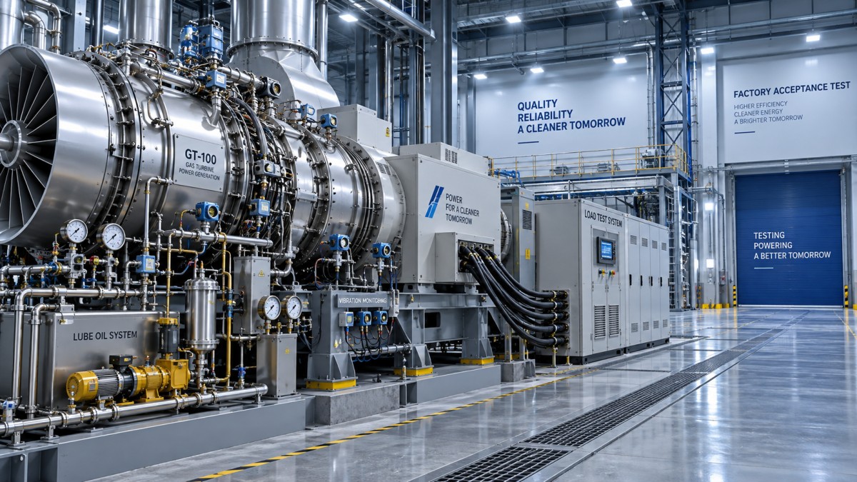
Calibration records matter here. Temperature, pressure, vibration, speed, electrical power, and fuel-flow measurements used for acceptance should be traceable to current calibration certificates. A test report with many decimal places is not necessarily reliable if the measurement chain, uncertainty, or calibration validity is unclear.
Observe operating behavior across the agreed load range
A stable no-load run is useful, but it does not prove that the package will handle a real operating duty. Where the factory facilities and contract scope allow, witness operation through the agreed load range, including loading and unloading steps. The purpose is not just to see the output rise. Watch how the governor, excitation system, fuel control, temperatures, vibration, and auxiliary pressures respond as the unit moves.
For a generator intended to operate in parallel with a grid or another generator, synchronization and load-sharing logic deserve close attention. Verify synchronizing permissives, voltage matching, frequency matching, phase sequence, breaker status feedback, active-power control, reactive-power or power-factor control, and the response to loss of a communication signal if that function is included. A manual demonstration is not a substitute for proving the automatic sequence specified for the project.
Load-step capability should be judged against the specified operating philosophy. An emergency generator may require a different response from a continuous industrial package. Review the recorded frequency and voltage behavior, recovery time, exhaust temperature margin, and any control limits reached during the step. If the manufacturer limits the factory test to a smaller step than the specified duty, that limitation should remain open on the punch list rather than disappearing into a general commissioning note.
Treat vibration and temperatures as trend information, not isolated numbers
Vibration readings are often reviewed as a pass/fail item, but their value is greater when they are interpreted as a pattern. Confirm the location and direction of each probe or pickup, the speed at which readings were taken, and whether the values are shaft-relative or casing vibration. Applicable vibration limits depend on the machine arrangement, bearing type, instrumentation, and referenced standard, so a generic limit copied from another package is not enough.
Look for abnormal changes during acceleration, loading, and coastdown. A value within an acceptance limit may still need investigation if it rises sharply at a particular speed or load. Similar caution applies to bearing metal temperatures, lube oil supply and return temperatures, exhaust temperature spread, cooling-air temperatures, and generator winding temperatures where measured. The concern is not merely whether one channel alarms; it is whether the thermal behavior is consistent across comparable points.
For units integrated into broader energy systems, the factory discussion should also consider the downstream operating regime. SINO-QNP’s turbomachinery scope includes gas turbines, compressors, generators, and steam-cycle equipment. In combined-cycle, waste-heat, heat-supply, biomass, or thermal generation projects, the operating constraints of a linked Steam Turbine can influence the gas turbine generator’s loading strategy, dispatch logic, and trip coordination. Those interfaces are not always fully testable in one factory run, but they should be reflected in the controls documentation and commissioning plan.
Protection and shutdown tests need disciplined witnessing
The most important factory test questions are often asked when the machine is not producing power. Verify which trips, alarms, interlocks, and permissives are physically tested and which are simulated. Both approaches can be acceptable when justified, but the report should distinguish them clearly.
Typical functions to review include overspeed protection, low lube oil pressure, high bearing temperature, high vibration, fire or gas shutdown inputs where supplied, emergency stop stations, generator electrical protection, loss of excitation where relevant, reverse power, overcurrent, over- and under-voltage, and over- and under-frequency. The required functions depend on the project scope and electrical protection scheme; not every relay function is tested in the same manner at the package factory.
Do not accept a statement that “all trips were checked” without supporting evidence. The test record should show the initiating condition, expected setpoint, actual action, alarm or trip annunciation, breaker response where applicable, fuel shutoff action, cooldown sequence, and reset requirements. It should also show that safety functions cannot be unintentionally bypassed through an operator screen or maintenance mode without controlled authorization.
Inspect controls, cybersecurity boundaries, and maintainability
A modern gas turbine generator package is as dependent on control logic as it is on mechanical hardware. Review the cause-and-effect matrix against the tested logic, check alarm priorities, and verify that local and remote control authority are understood. Confirm signal lists for plant DCS, switchgear, and emergency shutdown systems. A missing status point may not stop the factory test, but it can leave operators blind to a developing field issue.
Where remote access, data gateways, or third-party monitoring are included, clarify network ownership, access permissions, password handover, backup procedures, and the boundary between the package control system and the site network. This is increasingly a safety and availability matter, not merely an IT detail.
Walk around the package before release. Check access to filters, drains, valves, terminal boxes, inspection covers, lifting points, and routine maintenance areas. A component can be technically compliant yet impractical to service after installation if clearances were not considered. Verify preservation requirements for shipment, loose-item lists, special tools, recommended spares, and storage limitations. These details often determine whether a unit arrives ready for commissioning or requires avoidable remedial work.
Leave the factory with a controlled evidence package
The final deliverable should be more than a signed FAT certificate. Request the approved test procedure, raw and corrected performance records where relevant, calibration certificates, electrical test results, vibration data, protection test sheets, software and settings revision records, drawings marked with final revisions, inspection records, nonconformance reports, and a clear list of open items.
An open item is not automatically a reason to reject shipment. The practical question is whether it affects safety, performance, interface readiness, or future proof of compliance. Each item should have an owner, corrective action, verification method, and closure point—before shipment, during installation, or during site acceptance testing. Manufacturers with broad engineering, manufacturing, EPC, and service responsibilities, such as SINO-QNP, are generally best positioned when this handover is treated as a continuous record from design through commissioning rather than a one-day witness event.
A well-run factory test does not eliminate site risk. It does, however, prevent known issues from being shipped across a border, lifted onto a foundation, and discovered only when a plant schedule is already under pressure. That is the standard worth applying: every result should be traceable, every limitation should be visible, and every unproven function should have a defined plan for site verification.
- ▶ When an extraction steam turbine improves combined heat and power output
- ▶ What happens when process steam demand changes on an extraction steam turbine
- ▶ How to match extraction steam turbine pressure to process demand
- ▶ When local service coverage matters for a gas turbine generator manufacturer
- ▶ How manufacturer lead times can alter a gas turbine generator project
- ▶ Which certifications matter when choosing a gas turbine generator manufacturer
Search from here
Leave a message
