




















Why mud pump discharge pressure drops during continuous operation
A gradual drop in mud pump discharge pressure does not automatically mean the pump has failed. In a reciprocating mud pump, pressure reflects the resistance encountered by the delivered flow. A falling reading can therefore indicate reduced pump output, lower hydraulic resistance, leakage, or an inaccurate pressure signal. The most useful distinction is whether pressure falls while actual pump speed and delivered flow remain steady.
When considering what are common mud pump failures during continuous operation, suction starvation, worn valves, piston leakage, and liner damage deserve attention. However, drilling-fluid changes, an open bypass, or a downstream washout can produce similar symptoms. Increasing pump speed before identifying the cause can worsen cavitation, accelerate wear, or conceal a developing leak.
Establish what changed with the pressure
Compare the current condition with the last stable operating period: actual strokes per minute, discharge pressure, suction pressure, mud temperature, density, rheology, tank level, and flow indicators. Note any change in pump lineup, drilling depth, pipe movement, nozzle configuration, or valve position. Comparisons are meaningful only when the operating conditions are sufficiently similar.
Stroke count alone does not prove that the pump is delivering its expected volume. Theoretical output depends on displacement and speed; actual output also depends on how completely the cylinders fill and how effectively valves and seals prevent leakage. A pump can maintain its stroke rate while delivering less mud.
Use an independent pressure indication where available. A restricted pressure tapping or faulty transducer can mimic equipment deterioration. Do not loosen a gauge connection or clear a tapping while the system is pressurized.
Check whether the pump is being starved at the inlet
Suction problems can develop gradually during an otherwise steady run. A strainer accumulates solids, tank level drops, settled material restricts an outlet, or a suction hose deforms. If a charge pump is fitted, reduced charge pressure can also limit cylinder filling.
Inspect accessible indicators and external conditions: tank level, suction-valve position, hose condition, charge-pump operation, and suction-pressure trend. A low tank level can allow a vortex to draw air even before the inlet becomes uncovered. Leaking suction connections may admit air without showing an obvious outward mud leak.
Incomplete filling reduces delivered volume. Cavitation occurs when local pressure becomes low enough for vapor cavities to form; entrained air or gas can create similar unstable delivery without being the same mechanism. Both can produce fluctuating pressure and vibration, so sound alone is not a reliable diagnosis.
A restriction may become more apparent at higher stroke rates because the inlet cannot supply the required flow. Where permitted by the operating procedure, a controlled speed reduction can help establish whether instability is suction-related. It is not a repair: the restriction, inadequate charge pressure, or air-entry path still needs correction.
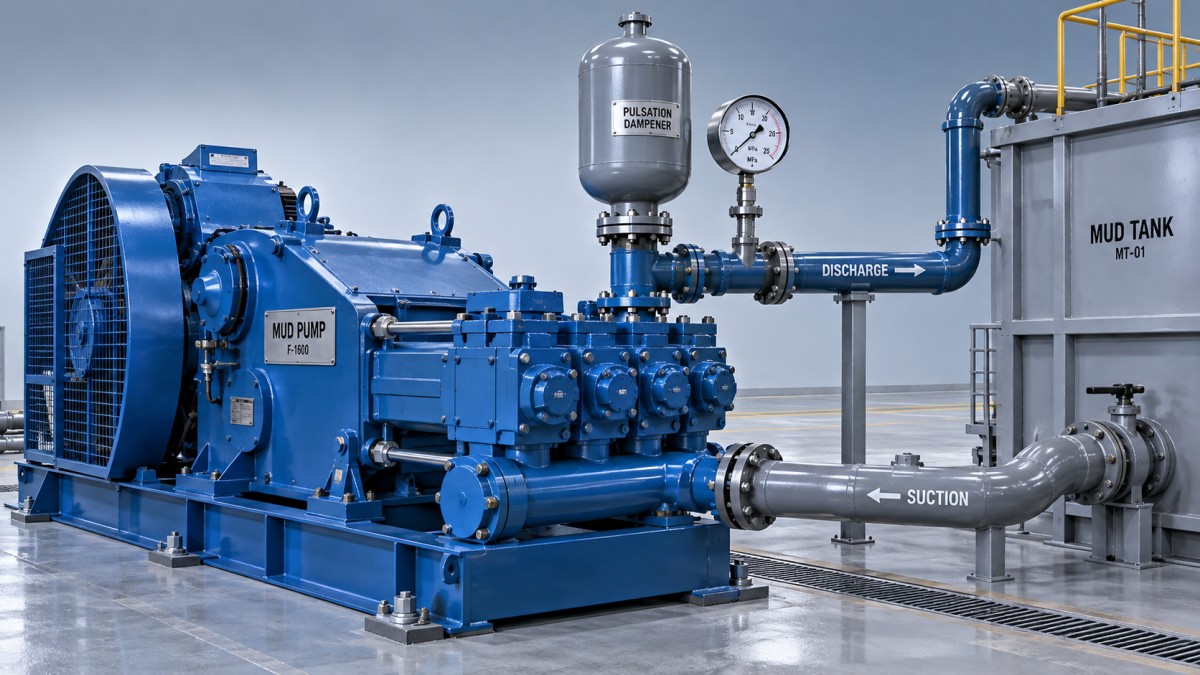
Recognize progressive fluid-end leakage
If suction conditions and actual pump speed are stable, declining output points more strongly toward the fluid end. Abrasive solids and repeated loading can damage valve sealing surfaces, pistons, and liners. Leakage then reduces volumetric efficiency, even though the power end continues to complete each stroke.
Valves that no longer seal properly
A damaged valve insert, eroded seat, broken spring, or trapped debris can prevent full closure. Discharge-valve leakage allows pressurized mud to return into a cylinder; suction-valve leakage can allow displaced mud to escape toward the inlet. Either reduces useful delivery and may create an uneven pressure waveform.
Changes in pulsation or knocking support this diagnosis but do not identify a particular valve conclusively. A pulsation dampener problem can also increase pressure fluctuations without causing the same loss of average output. Valve inspection requires shutdown, isolation, and verified depressurization.
Piston and liner wear
Worn piston seals or damaged liner surfaces allow mud to bypass the piston. Leakage may become more pronounced as the components heat up, while inadequate piston cooling or flushing—where fitted—can accelerate damage. Check the specified cooling or wash system for correct flow and condition.
Depending on pump design, abnormal leakage may be visible at designated drains or the liner area. Observe only from a safe position with guards in place. Do not approach a suspected high-pressure leak to locate it by touch. When dismantling is necessary, inspect the piston and liner together: replacing a seal without addressing a scored or excessively worn liner may leave the underlying problem unresolved.
Separate mud changes from pump deterioration
Mud temperature and rheology affect circulation pressure. If warming or treatment reduces viscosity or yield stress, pressure can decline even when delivered flow remains unchanged. Changes in density also affect the system, although a surface-pressure reading cannot by itself determine which fluid property changed.
Compare representative mud measurements with the pressure trend rather than assuming that every gradual decline is mechanical wear. Keep the distinction between circulating pressure and hydrostatic pressure clear: a lower discharge reading is not, on its own, evidence of reduced mud density.
Fluid changes can also impair pump filling. Higher viscosity increases inlet losses, while gas-contaminated mud makes delivery less consistent. Thus, a mud-related pressure drop may represent either reduced downstream resistance or reduced pump output. Flow information and suction conditions help separate those mechanisms.
Do not overlook bypasses and downstream washouts
A bypass valve, relief device, or manifold connection can divert flow from the intended circulation path. Check valve positions and available return-path indications against the approved operating lineup. A relief device that leaks below its intended operating pressure requires investigation, not adjustment simply to recover the gauge reading.
If pump speed and delivery remain stable but pressure falls unexpectedly, investigate downstream integrity. A surface-line leak, drillstring washout, or changed nozzle condition can reduce resistance. In a drilling operation, the significance depends on the pressure trend, return flow, pit volume, and current activity.
An unexplained pressure drop accompanied by abnormal returns or pit-volume changes must be handled under the site's drilling and well-control procedures. Do not continue troubleshooting the pump in isolation or increase speed merely to restore the previous pressure. A developing washout can enlarge while the equipment continues to run.
Confirm the repair under controlled conditions
Stop or escalate promptly when pressure loss is accompanied by a visible high-pressure leak, severe knocking, overheating, worsening vibration, or abnormal well indicators. Before opening the fluid end or suction system, isolate the equipment, apply lockout/tagout, and verify that trapped pressure has been released. Pulsation dampeners and other stored-energy devices require their own manufacturer-specified precautions.
After correcting the identified cause, restart according to the approved procedure and increase speed progressively. Compare pressure, actual speed, suction conditions, and delivered flow at a repeatable operating point. Confirm that leakage, vibration, and cooling-system behavior are acceptable.
Recovered pressure alone is not sufficient proof of a successful repair: pressure can rise because resistance has increased while delivery remains inadequate. The stronger confirmation is restored flow at comparable mud properties and circuit conditions, with stable suction and no abnormal mechanical symptoms. Recording those conditions provides a useful baseline for detecting the next gradual loss before it becomes a major interruption.
- ▶ How waste heating value fluctuations affect WTE turbine output
- ▶ What causes mud pump bearings to overheat during continuous operation?
- ▶ Why mud pump discharge pressure drops during continuous operation
- ▶ Should you lease or buy a mud pump for recurring short-term projects?
- ▶ Does mud pump resale value justify buying for a short-term project?
- ▶ How project extensions change the mud pump lease-or-buy decision
Search from here
Leave a message
