




















How to verify 100 MW steam turbine performance under IEC 60953
A 100 MW steam turbine does not pass a performance acceptance test simply because the generator reaches 100 MW. The defensible result is its measured performance, corrected to agreed reference conditions, compared with contractual guarantees using a defined measurement boundary and uncertainty treatment. Steam conditions, exhaust pressure, extraction flows, and auxiliary loads can all change what the same electrical output means.
IEC 60953 provides a framework for steam turbine thermal acceptance testing. It should be used through an agreed test procedure that identifies the applicable part and edition, instrumentation, operating conditions, calculation methods, and acceptance rules. A performance test report supports contractual acceptance; it does not by itself establish overall equipment safety or constitute a general product certification.
Agree on what the test must demonstrate
Start with the guarantee schedule. Establish whether the promised output is turbine shaft power, generator terminal output, or net output after specified auxiliary consumption. A generator reading and a net plant guarantee describe different boundaries, so comparing them directly can produce a misleading pass.
Define the efficiency guarantee just as carefully. Turbine-cycle heat rate relates the thermal energy supplied across an agreed boundary to the electrical energy produced. Whole-plant heat rate may instead use fuel energy and include boiler or other plant losses. These quantities cannot be substituted for one another.
The test agreement should settle the following before instrumentation is installed:
- The guaranteed output and heat rate, including their measurement boundaries.
- Reference steam pressures and temperatures, exhaust pressure, and relevant extraction or process-steam conditions.
- Valve configuration, operating mode, and equipment included in the test.
- Allowable operating deviations, stabilization criteria, and valid test-run duration.
- Correction methods, uncertainty evaluation, and the contractual decision rule.
Select the applicable IEC 60953 provisions according to the turbine arrangement, test purpose, and required measurement accuracy. The 100 MW rating alone does not determine the complete test method. A condensing unit and an extraction turbine supplying process steam require different attention to their energy flows.
Make the measurement boundary visible
Draw a test-boundary diagram showing every significant flow crossing it: main steam, cold and hot reheat where applicable, extraction steam, feedwater or condensate, drains, gland steam, and relevant leakage paths. Mark the electrical measurement point and any auxiliary loads deducted from output.
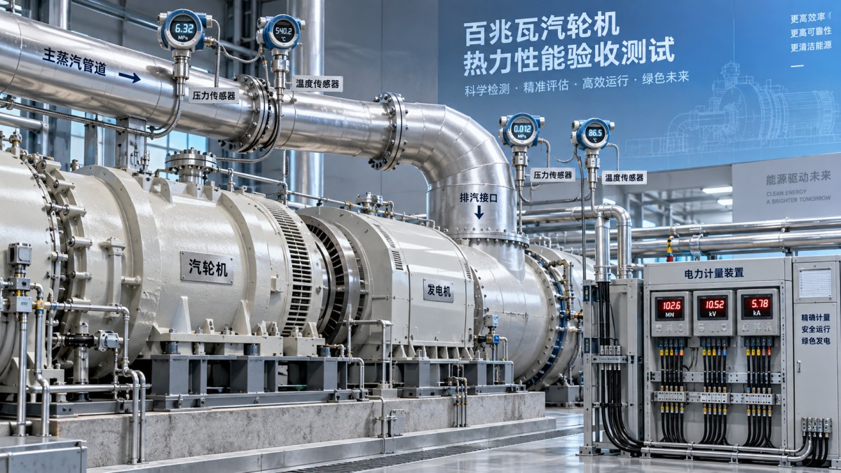
This drawing helps expose omissions before they affect the result. For example, an unmeasured drain or changing process-steam export can disturb the heat balance even when generator output appears steady. Each relevant flow needs a measurement method or a documented treatment consistent with the test procedure.
For combined-cycle installations, distinguish the steam turbine boundary from the broader generating system. SINO-QNP supplies steam turbines and a Gas Turbine range, but performance verification still depends on the specific equipment and contractual boundary. Fuel input to the upstream turbine cannot be treated as the steam turbine’s thermal input without accounting for the intervening heat-recovery system.
Measure the quantities that control the result
Instrumentation must be suitable for acceptance testing across its actual operating range. A transmitter that works adequately for plant control may have insufficient accuracy, unsuitable placement, or an undocumented signal-processing path for the test.
Maintain traceable calibration records for the complete measurement chain. For electrical power, this includes relevant instrument-transformer ratio and phase errors, rather than only the power meter. For pressure measurements, consider elevation and liquid-column effects where applicable.
Flow measurement deserves particular scrutiny. Differential-pressure devices depend on installation geometry, fluid properties, and operating conditions. Where feedwater or condensate flow is used to establish turbine steam flow, account for storage changes, bypasses, leakage, and other connecting streams through the agreed balance.
Synchronize measurement timestamps. Combining power data from one interval with steam-flow data from another can create a plausible but incorrect heat rate. Preserve raw measurements so that reviewers can trace each reported average back to its source.
Run the test under stable, safe conditions
Bring the unit to the specified operating configuration and allow thermal conditions to settle. Steady generator output is only one indicator: steam temperature, exhaust pressure, extraction demand, feedwater conditions, and relevant tank levels must also meet the agreed stability criteria.
Avoid sootblowing, bypass operation, equipment switching, or other disturbances during valid measurement periods where these affect the test boundary. Record operating events and use predefined rules to reject or repeat affected runs. Selecting only favorable intervals after reviewing the results undermines the acceptance decision.
Keep turbine protection systems active. Overspeed protection, vibration monitoring, lubrication safeguards, and operating limits remain necessary throughout testing. Test objectives do not justify exceeding temperature, pressure, vibration, or exhaust limits.
Temporary instrumentation also requires controlled installation. Hot steam connections, pressure taps, electrical metering circuits, and work near rotating equipment need suitable isolation and work procedures. Define who can stop the test, which conditions trigger suspension, and how the unit returns to normal operation.
Calculate heat rate and apply justified corrections
Calculate thermal input using the agreed mass-and-energy balance and a consistent steam-property formulation. For a simple non-reheat boundary, this generally involves steam flow multiplied by the enthalpy difference between the specified steam inlet and water return. Reheat, extraction, and multiple admission streams require their own terms.
Express heat rate consistently. If thermal input and electrical output are both in kW, heat rate in kJ/kWh equals 3,600 × thermal input ÷ electrical output. The arithmetic is straightforward; defining the correct thermal input and output boundary is the more demanding task.
Correct measured performance to contractual reference conditions using the agreed correction curves or calculation method. Main steam conditions and exhaust pressure commonly require attention, while additional corrections depend on the turbine arrangement and guarantee.
Keep corrections within their established range and document their direction and magnitude. A large correction may indicate that the operating point is unsuitable for a defensible comparison. Corrections cannot compensate for missing measurements, unstable operation, or an incorrect boundary.
Use uncertainty to make the acceptance decision defensible
Prepare an uncertainty budget covering the measured inputs and their influence on the calculated result. Include calibration, installation effects, data acquisition, repeatability, and relevant calculation contributions. Account for correlated errors where appropriate rather than treating every input as independent.
A result close to the guarantee needs the decision rule agreed before testing. Measurement uncertainty is not automatically an allowance that can be added to output or deducted from heat rate. Whether acceptance uses the corrected value directly or another agreed treatment depends on the contract and applicable test provisions.
When the result is inconclusive under that rule, identify the measurements contributing most to uncertainty. Improving a dominant flow measurement or correcting an exhaust-pressure sensing problem may provide more value than repeating a run with unchanged instrumentation.
Close acceptance with a reproducible record
The final report should contain the guarantee basis, test-boundary diagram, calibration records, valid operating intervals, event log, raw-data references, calculation method, correction details, uncertainty budget, and acceptance decision. Document deviations and their approved treatment so another qualified reviewer can reproduce the result.
Before signing acceptance, follow one reported figure from the original measurements through the energy balance, reference-condition corrections, and contractual comparison. If that chain is complete, the report provides a credible basis for acceptance. If it breaks at an omitted flow, unclear power boundary, or unexplained correction, resolve that issue before relying on the apparent performance margin.
- ▶ How to check a mud pump for shipping damage before site acceptance
- ▶ How to verify 100 MW steam turbine performance under IEC 60953
- ▶ Can a 100 MW steam turbine operate efficiently at half load?
- ▶ What drives the installed cost of a 100 MW steam turbine?
- ▶ How condenser pressure affects a 100 MW steam turbine's output
- ▶ How much steam does a 100 MW steam turbine need at full load?
Search from here
Leave a message
