




















How does partial admission affect an impulse steam turbine?
Partial admission affects an impulse steam turbine by supplying steam through only part of the nozzle circumference. It can reduce part-load throttling losses compared with regulating every nozzle through a common throttle, but it also introduces windage, sector-edge losses, and repeated blade loading. The efficiency benefit is therefore conditional: reduced throttling must outweigh the additional aerodynamic losses, while blade stresses remain within the design limits.
This trade-off matters when a turbine spends substantial time below rated output. A change in nozzle-group operation may improve steam consumption at one load yet produce an efficiency dip or stronger vibration at another. The useful assessment is not simply whether partial admission is available, but how each admission pattern behaves across the expected operating range.
Admission fraction is not the same as turbine load
The admission fraction is the proportion of the nozzle circumference actively supplying steam to a particular stage. For circumferentially distributed nozzles, it can be expressed as ε = active admission arc / total circumference. Nozzle-group governing changes the effective admission area by opening or closing valves serving separate groups.
In an impulse stage, most of the stage pressure drop occurs in the stationary nozzles. The moving blades extract work by turning and slowing the resulting jets. Under partial admission, each blade repeatedly passes through an active steam sector and then an inactive sector instead of experiencing approximately continuous circumferential flow.
Admission fraction alone does not determine mass flow or output. Nozzle throat area, upstream steam conditions, downstream pressure, valve opening, and choking conditions also matter. Two arrangements with the same active arc can have different flow capacities and losses.
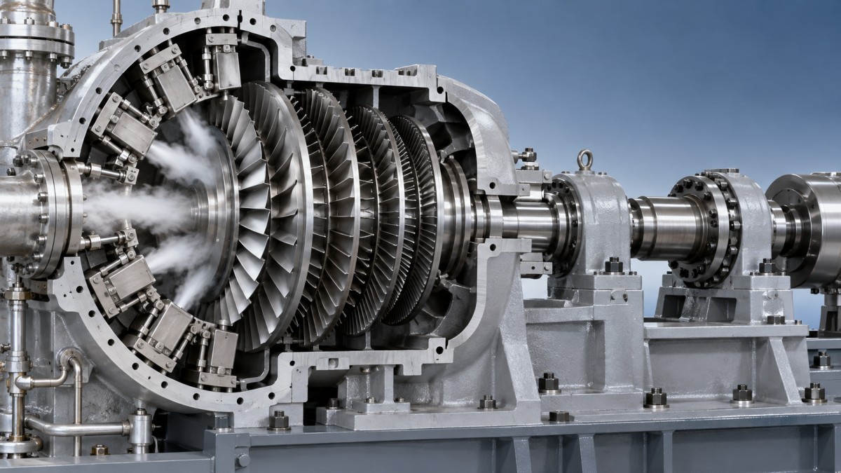
Partial admission is often concentrated in the governing stage rather than applied identically throughout the turbine. Downstream stages receive flow that redistributes circumferentially, although nonuniformity may persist. A governing-stage efficiency change should therefore not be treated as an equal change in whole-turbine efficiency.
Where the part-load efficiency advantage comes from
With common-valve throttling, reducing load lowers the pressure supplied to all nozzles. Throttling is approximately isenthalpic, but it increases entropy and reduces the work potential available to the turbine. Nozzle-group governing can instead close selected groups while keeping the open groups closer to their intended inlet conditions.
That distinction explains why partial admission can be attractive for variable-load service. It does not mean the open groups always operate without throttling. During sequential valve opening, one group may be partially open while others are fully open or closed. Valve pressure losses, governing-stage pressure ratio, and downstream conditions then change together.
For a meaningful comparison, use matching inlet steam conditions, exhaust pressure, speed, and output basis. Evaluate the complete turbine, including relevant mechanical losses and auxiliary consumption. A design-point stage calculation cannot establish which governing strategy consumes less steam over an actual duty cycle.
Losses that offset reduced throttling
- Inactive-sector windage: Blades passing through non-admitted regions stir and accelerate the surrounding fluid without receiving useful jet work. The loss depends on speed, fluid density, blade geometry, and the inactive arc.
- Filling and emptying losses: Blade passages entering and leaving an active sector undergo transient flow establishment and decay. These effects become more significant when sector boundaries are numerous relative to the admitted arc.
- Sector-edge mixing: Jets near admission boundaries interact with lower-momentum fluid, producing nonuniform velocity, incidence, and dissipation.
As admission becomes very small, parasitic losses can consume a larger share of the useful stage power. There is no universal admission fraction below which performance becomes unacceptable. The applicable limit depends on the stage geometry, operating conditions, and minimum-load requirements.
Nozzle arrangement changes both losses and excitation
Equal admission fractions do not guarantee equal performance. One contiguous active sector and several separated sectors create different numbers of entry and exit boundaries. Dividing admission into more sectors can increase boundary-related losses, while changing circumferential force distribution and the frequency content of blade excitation.
A small number of large sectors may reduce the number of boundaries, but can produce stronger low-order flow nonuniformity. Distributed sectors may improve circumferential balance, yet expose each blade to more loading transitions per revolution. Neither arrangement is automatically superior; aerodynamic and structural assessments must use the actual valve-opening sequence.
Nozzle velocity also changes with pressure ratio. The blade-speed-to-jet-speed relationship and inlet incidence can therefore move away from their design values as valves operate. Preserving pressure in an open nozzle group does not guarantee optimal velocity triangles throughout the governing range.
Periodic blade loading is a fatigue issue, not just a vibration issue
Each moving blade experiences a rise in aerodynamic force when it enters an admitted sector and a reduction when it leaves. The resulting excitation contains harmonics related to rotational speed and the admission pattern. Sector widths, spacing, and valve states influence that spectrum.
When an excitation component approaches a blade or blade-group natural frequency, dynamic stress can increase. Assessment should consider mode shapes, damping, shroud or lacing behavior where applicable, and hot operating conditions. A Campbell diagram is useful, but identifying a frequency crossing alone does not establish the stress amplitude or fatigue acceptability.
Low bearing vibration does not prove that blade dynamic stress is low. Local blade modes may not produce a strong response at casing or bearing sensors. Conversely, elevated overall vibration may arise from imbalance, alignment, bearings, or other causes rather than partial admission.
For sustained variable-load service, request confirmation that the permitted admission combinations and relevant transitions have been covered by the blade excitation assessment. Repeated operation near a problematic condition can matter more than a brief passage through it.
Investigating an efficiency dip or vibration change
When a symptom appears near a nozzle-group transition, first establish whether it follows the valve state or another operating variable. Compare steady operating points with matched steam conditions and exhaust pressure rather than relying on output alone.
- Record the admission state. Capture individual valve positions, valve-chest or nozzle-group pressures where available, speed, steam flow, and power. Check that actual valve movement agrees with the commanded sequence.
- Separate transient and steady behavior. A short disturbance during valve movement differs from persistent losses or excitation after conditions stabilize.
- Review vibration spectra. Compare frequency components before and after the transition. Relate changes to shaft orders, the admission pattern, and identified modes rather than only to overall amplitude.
- Check competing causes. Valve leakage, sticking, steam-condition changes, exhaust-pressure variation, and measurement error can resemble an admission-related problem.
Do not modify valve overlap or opening order solely to remove an efficiency dip. Such changes can alter excitation, governing stability, and load response. Adjustments should remain within the manufacturer’s approved operating map and control procedures.
What to request before accepting a variable-load design
A useful technical submission includes guaranteed performance at representative loads, the corresponding valve combinations, minimum continuous load, and any restricted operating regions. It should distinguish governing-stage calculations from complete-machine performance and state the assumptions used for partial-admission losses.
Performance comparisons also need agreed measurement boundaries and correction methods. Steam rate, shaft power, and electrical output are not interchangeable. Inlet conditions, exhaust pressure, extraction flows where applicable, and uncertainty treatment should be defined before judging competing proposals.
At plant level, the evaluation may also include a different prime mover. The supplied Gas Turbine range offers models with listed outputs from 2 to 114.5 MW and model-dependent fuel options. This is a separate architecture comparison, not a remedy for steam-stage admission losses: steam availability, fuel supply, heat demand, and part-load performance must be assessed independently.
For the steam turbine itself, the decisive evidence is a supported operating map linking output, valve state, steam consumption, and permissible operation. A favorable rated efficiency is insufficient when the intended duty places substantial running time at partially admitted loads or near nozzle-group transitions.
- ▶ Why an impulse steam turbine loses power when steam pressure drops
- ▶ How does partial admission affect an impulse steam turbine?
- ▶ When should you choose an impulse steam turbine over a reaction design?
- ▶ How does an impulse steam turbine convert steam into shaft power?
- ▶ When a 50 MW steam turbine fits an industrial captive power plant
- ▶ How to assess overload capability in a 50 MW steam turbine
Search from here
Leave a message
