




















How does an impulse steam turbine convert steam into shaft power?
How does an impulse steam turbine convert steam into shaft power?
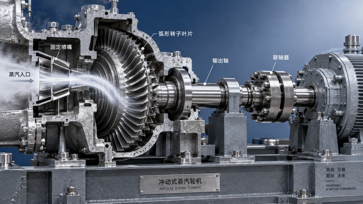
An impulse steam turbine converts steam energy into shaft power through two distinct steps. Stationary nozzles expand high-pressure steam into fast-moving jets. Curved blades attached to a rotor then redirect those jets, transferring momentum to the rotor and producing torque. The shaft carries that torque to a generator, compressor, or other driven equipment.
The distinction matters: the nozzles accelerate the steam, while the moving blades extract work from it. Understanding what happens in each component explains why inlet steam conditions, blade speed, exhaust pressure, and operating load all affect the power available at the shaft.
The nozzle turns steam enthalpy into velocity
Steam entering a turbine carries energy associated with its pressure and temperature, described thermodynamically by enthalpy. As it passes through a stationary nozzle, its pressure falls and its velocity rises. The nozzle directs the resulting jet toward the rotor blades at a carefully selected angle.
In an ideal nozzle, the decrease in steam enthalpy becomes an increase in kinetic energy. Real nozzles introduce friction and other flow losses, so the actual jet velocity is lower than an ideal expansion would predict. Nozzle geometry must suit the intended pressure ratio and steam flow; increasing inlet pressure alone does not guarantee a proportional increase in useful output.
For an ideal impulse stage, the stage pressure drop occurs in the stationary nozzles, with approximately constant static pressure across the moving blade row. This distinguishes it from a reaction stage, where expansion also occurs within the rotor passages. Real machines have more complex pressure distributions, but the distinction remains useful when interpreting their design.
Changing steam direction creates rotor torque
The steam jet enters a passage between moving blades and follows their curvature. As the blades turn the flow, they change its momentum. The corresponding force acts on the blades, and its tangential component creates torque around the shaft axis.
This is more precise than saying steam simply “hits” the rotor. Efficient operation depends on controlled flow through the blade passages, not blunt impact. Blade inlet angles must match the steam velocity relative to the moving rotor. Poor alignment causes incidence losses and can encourage flow separation.
At a representative blade radius, the energy transfer can be expressed as rotor power = steam mass flow × blade speed × change in tangential steam velocity. Here, tangential velocity means the component measured in the stationary frame around the shaft. Engineers use velocity triangles to relate this component to blade speed and the steam’s relative velocity.
The relationship explains why speed matching is essential. A stationary rotor may experience torque, but it produces no mechanical power because it is not rotating. At an unsuitable operating speed, the blades cannot extract the available jet energy efficiently. Some energy also leaves with the exhaust steam rather than becoming shaft work.
Why industrial turbines use multiple stages
Expanding steam through a large pressure drop in one nozzle row can produce very high jet velocities. Extracting that energy efficiently in a single moving row would require a high blade speed, creating mechanical and aerodynamic challenges. Staging spreads the energy conversion across several blade rows.
In pressure compounding, successive nozzle-and-rotor stages divide the overall pressure drop. Each nozzle row accelerates the steam, and each moving row extracts part of its energy. In velocity compounding, one nozzle expansion is followed by multiple moving rows, with stationary guide blades between them to redirect the flow.
These arrangements involve different trade-offs in efficiency, speed, size, and complexity. As steam expands, its specific volume generally increases, so downstream flow passages must accommodate a larger volumetric flow. A practical turbine is therefore not simply a repeated stack of identical blades.
What determines usable shaft output?
The rotor’s aerodynamic power is not the same as the power delivered to the driven machine. Bearing friction and other mechanical losses reduce shaft output. If the turbine drives a generator, generator losses further reduce electrical output; a gearbox, where fitted, introduces another efficiency boundary.
Several operating conditions deserve attention when assessing performance:
- Steam flow and inlet state: Mass flow, pressure, and temperature establish the available energy and must be evaluated together.
- Exhaust pressure: Lower exhaust pressure generally permits more expansion, but condenser capability, cooling conditions, and exhaust moisture constrain the result.
- Internal clearances: Leakage through seals and blade-tip gaps allows steam to bypass useful energy transfer.
- Blade and nozzle condition: Deposits, erosion, and surface damage alter flow angles and increase losses.
- Part-load operation: Throttling and admission control change the conditions entering the stages, so rated efficiency should not be assumed across the full operating range.
Steam quality is also an equipment-protection issue. Liquid carryover can damage components, while moisture formed during expansion can contribute to blade erosion. Drainage, suitable inlet steam conditions, and disciplined startup procedures matter alongside the aerodynamic design. Overspeed protection remains essential because a sudden loss of driven load can allow rapid rotor acceleration.
Impulse describes the stage, not the whole plant duty
An impulse steam turbine can serve different plant arrangements. A condensing unit expands steam toward a low-pressure exhaust to obtain more shaft work. A back-pressure unit exhausts at a pressure suitable for downstream process heating. Extraction arrangements remove some steam at intermediate pressure while the remaining flow continues through the turbine.
For a plant needing both electricity and heat, maximizing turbine output in isolation may be the wrong objective. Process steam demand can determine exhaust pressure and extraction flow. In biomass generation, waste-to-energy, waste heat utilization, and combined-cycle applications, the turbine must match the steam source and the plant’s operating schedule.
SINO-QNP’s Steam Turbine offering includes impulse and reaction designs, with condensing, extraction-condensing, back-pressure, and extraction-back-pressure configurations. Those categories describe different decisions: stage working principle governs energy transfer, while exhaust and extraction arrangements govern how the turbine integrates with power and heat demand.
From working principle to a useful technical discussion
A meaningful turbine assessment starts with inlet pressure and temperature, available steam flow, exhaust requirements, driven-equipment speed, and the expected load profile. These inputs help establish whether the proposed arrangement can deliver the required shaft duty without sacrificing necessary process heat.
SINO-QNP brings over 30 years of turbomachinery experience across steam turbines, gas turbines, compressors, and generators. Its scope spans R&D and design, manufacturing and sales, EPC projects, and spare parts, supported by a global marketing and service network. For an industrial drive or generating installation, that scope is relevant to shaft-train integration, project delivery, and maintenance planning—not just turbine selection.
The conversion principle is straightforward: expansion creates velocity, blade turning creates torque, and rotation delivers power. Whether a particular installation uses that energy well depends on matching the turbine to real steam conditions, speed requirements, and the plant’s heat balance.
- ▶ Why an impulse steam turbine loses power when steam pressure drops
- ▶ How does partial admission affect an impulse steam turbine?
- ▶ When should you choose an impulse steam turbine over a reaction design?
- ▶ How does an impulse steam turbine convert steam into shaft power?
- ▶ When a 50 MW steam turbine fits an industrial captive power plant
- ▶ How to assess overload capability in a 50 MW steam turbine
Search from here
Leave a message
