




















What should a mud pump trial run confirm before site acceptance?
What should a mud pump trial run confirm before site acceptance?
A mud pump that runs smoothly during a brief demonstration may still fall short of site acceptance requirements. Knowing how to inspect a mud pump before accepting delivery at site means checking more than startup alone. A controlled trial run should confirm specified pressure and flow, stable lubrication, acceptable vibration and temperature, sound connections, and functioning guards, alarms, and shutdown systems. The evidence must support a documented handover decision—not simply show that the machine can turn.
Agree on what “accepted” means before starting
The purchase specification, approved datasheet, manufacturer’s operating instructions, and project inspection and test plan should define the acceptance basis. Applicable standards must be checked against the equipment type and contract; a standard covering design or factory testing does not automatically establish every site trial requirement.
Agree on the test fluid, operating points, run duration, measurement locations, permissible deviations, and witness requirements. If the contract leaves these open, resolve them before testing. There is no universal trial duration or vibration limit suitable for every reciprocating mud pump installation.
Fluid conditions matter. Water testing may demonstrate mechanical operation and basic hydraulic performance, but it does not necessarily represent operation with heavier, more viscous, or solids-laden mud. Record fluid density, temperature, and relevant rheological properties. Any difference from the specified service fluid needs an agreed interpretation, not an undocumented assumption.
Establish a safe, testable installation
Before energizing the drive, verify the delivered model, serial number, liner and piston configuration, and pressure rating against approved documents. Inspect for transport damage, loose fasteners, disturbed alignment, and preservation materials left in operating passages. Confirm foundation security and piping support so external loads do not distort the pump connections.
- Check lubricant grade, level, filter condition, and any required pre-lubrication system.
- Confirm adequate suction supply, priming, liner cooling or flushing where fitted, and an unobstructed return path.
- Verify guards, electrical grounding, emergency-stop access, and safe separation from pressurized equipment.
- Check that hoses, manifolds, fittings, and instruments are suitable for the planned pressure and fluid.
- Verify relief-device settings and discharge routing, plus pulsation-dampener condition and precharge where applicable, using the manufacturer’s procedure.
A positive-displacement pump must not be deadheaded to prove pressure capability. Use an engineered test circuit with controlled loading and pressure protection. Establish stop conditions and exclusion zones before the run, and never search for a high-pressure leak by hand.
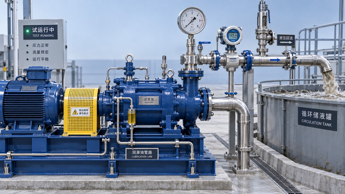
Prove pressure and flow together
Begin at the manufacturer’s prescribed startup condition, with the fluid end supplied and auxiliaries operating. Confirm rotation through an approved method, then increase speed and load in controlled stages. Pause at agreed operating points long enough to obtain stable readings and observe trends.
At each point, record pump speed or stroke rate, suction pressure, discharge pressure, measured flow, and drive load. Pressure alone is insufficient: a pump can develop pressure while delivering less than the required volume. Conversely, adequate flow at low resistance does not prove performance at working pressure.
Compare delivered flow with the expected displacement for the installed liner size, stroke, and speed. Investigate unexplained shortfall rather than accepting a calculated theoretical value as measured output. Valve leakage, piston or liner wear, air entry, poor suction conditions, and measurement error can all affect the result.
Reciprocating pumps produce pressure pulsation. Instrument selection and sampling must distinguish normal pulsation from unstable operation without filtering away significant peaks. Record where pressure is measured; a dampened gauge reading alone may not reveal stresses elsewhere in the discharge system.
Watch trends, not just isolated readings
A short demonstration may end before bearing, gearbox, or lubricant temperatures stabilize. Continue for the agreed duration and assess whether temperatures settle within manufacturer limits. A reading below an alarm threshold is not reassuring if it keeps rising without approaching a stable condition.
Observe lubrication pressure and temperature under load, not only at startup. Foaming, interrupted supply, unexpected filter indications, or abnormal oil contamination require investigation. Record measurement locations and ambient conditions so later comparisons remain meaningful.
Vibration assessment needs similar discipline. Use repeatable measurement positions and criteria appropriate to the reciprocating machine and its mounting arrangement. Do not automatically apply limits intended for unrelated rotating equipment. New knocking, foundation movement, or a sudden change with load warrants a controlled stop even when an overall vibration reading appears acceptable.
Inspect connections from a safe position throughout the run. Distinguish prohibited external leakage from any manufacturer-permitted packing seepage or designed drainage. Record the location and operating condition of each finding. Tightening a pressurized joint or adjusting moving components is not an acceptable troubleshooting shortcut.
Demonstrate protection without creating a fault
Alarm and shutdown checks should follow an approved cause-and-effect schedule. Where fitted, verify low lubrication pressure, excessive temperature, drive overload, and other specified protections through safe simulation or manufacturer-approved testing. Do not deliberately starve lubrication, obstruct suction, or overpressure the circuit to trigger a response.
Check the complete response: detection, alarm indication, shutdown action, event recording, and reset behavior. An alarm appearing on a screen does not prove that the drive stops. Emergency-stop testing should also confirm that restarting requires the intended deliberate action. Relief-device verification is separate from control-system shutdown testing; record evidence for both.
Keep the drive and pump acceptance boundaries clear
Where a pump forms part of a larger power-equipment package, hydraulic acceptance and driver acceptance remain separate obligations. SINO-QNP’s more than 30 years in turbomachinery, covering gas turbines, steam turbines, compressors, and generators, provides relevant context for coordinating equipment interfaces. Its scope spans R&D, design, manufacturing, sales, EPC projects, and spare parts, supported by a global marketing and service network.
For projects considering a Steam Turbine for industrial drive service, confirm speed matching, coupling arrangements, governing, lubrication interfaces, and shutdown coordination separately. Impulse or reaction designs and condensing or back-pressure configurations require application-specific selection; none replaces proof of the pump’s own hydraulic performance.
Make the handover decision traceable
The trial report should identify the tested configuration, calibrated instruments, fluid conditions, operating points, trends, protection-test results, and witnessed exceptions. Attach relevant calibration evidence and distinguish site measurements from factory records.
After shutdown, isolate and depressurize before checking loosened connections, abnormal wear indications, contamination, or new leakage. List unresolved defects with an owner, corrective action, and retest requirement. Conditional acceptance should state operating restrictions explicitly; unresolved safety or required-performance failures should not be reduced to routine punch-list items. Sign acceptance only when the evidence matches the agreed criteria and any limitations are visible in the handover record.
- ▶ What should a mud pump trial run confirm before site acceptance?
- ▶ Which records should you verify before accepting a mud pump on site?
- ▶ How to check a mud pump for shipping damage before site acceptance
- ▶ How to verify 100 MW steam turbine performance under IEC 60953
- ▶ Can a 100 MW steam turbine operate efficiently at half load?
- ▶ What drives the installed cost of a 100 MW steam turbine?
Search from here
Leave a message
