




















What foundation conditions are needed for a 50 MW steam turbine
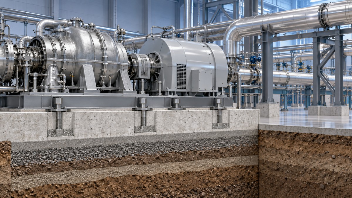
A foundation for a 50 MW steam turbine must do more than carry the machine's static weight. It must hold the turbine-generator train in stable alignment while resisting dynamic forces, limiting vibration transmission, accommodating thermal movement, and remaining reliable as soil and operating conditions change. For quality and safety control, the central question is whether the complete foundation-soil system behaves as designed, not whether the concrete block simply looks substantial.
The final arrangement must follow the turbine OEM's load data, allowable vibration criteria, anchor-bolt layout, and erection requirements. Civil drawings cannot be treated as independent of the turbine package: rotor dynamics, bearing locations, generator coupling, condenser connections, piping reactions, and auxiliary skids all influence the foundation design and acceptance work.
Start with the ground, not the concrete
Geotechnical investigation is the first condition. The investigation needs to establish whether the supporting strata can carry the combined dead load, operating load, transient load, and any seismic or site-specific environmental loads without unacceptable settlement or differential settlement.
Uniform support is usually more important than a single favorable bearing-capacity figure. A foundation may be acceptable in overall bearing pressure yet still create serious alignment problems if one side settles more than the other. Differential movement can change bearing elevations, distort the turbine casing support line, and load the coupling between turbine and generator. These effects may appear gradually after commissioning, making them easy to misattribute to balancing or bearing defects.
Quality teams should ensure that the ground report addresses soil layering, groundwater conditions, compressibility, seasonal moisture changes, possible liquefaction where relevant, and the effect of nearby structures or excavation. Fill material beneath a turbine hall deserves particular scrutiny. Engineered, tested fill may be suitable when properly designed; uncontrolled fill is not a sound basis for a high-speed rotating machine foundation.
Foundation mass and stiffness must work together
A 50 MW steam turbine is normally installed on a reinforced-concrete foundation or structural pedestal system designed specifically for the equipment train. Mass helps reduce response to dynamic forces, but mass alone does not solve vibration problems. The structure also needs sufficient stiffness to prevent local bending, twisting, or uneven movement at bearing pedestals, soleplates, and anchor locations.
The foundation design should consider the whole dynamic path: rotating equipment, base frame or soleplates, concrete structure, soil, and connected piping. A flexible support can amplify vibration even when the rotor itself is properly balanced. Conversely, an excessively simplified “heavier is better” approach can overlook resonance and create construction, settlement, or maintenance-access issues.
Dynamic analysis should evaluate the foundation's natural frequencies against the expected operating and transient excitation frequencies of the turbine-generator train. The objective is to avoid operating near a resonant condition. This evaluation must include the actual supported equipment configuration, because the installed generator, exciter, gear unit if used, and auxiliaries change the system response.
Control vibration at the source and at the boundary
Vibration acceptance should not begin only after the turbine is running. The foundation needs defined inspection points before grouting, after grouting, during alignment, and during commissioning. Surface defects, honeycombing around anchor pockets, poor grout contact, unrestrained embedded items, or inconsistent bearing areas can become vibration paths or local compliance points.
For most turbine foundations, isolation is not a separate layer added casually beneath the machine. The required arrangement depends on the turbine's mounting concept and the building structure. Some installations use a rigid common foundation; others require separation joints or specially engineered vibration-control measures to prevent transmission to adjacent equipment or structures. Introducing resilient material without the OEM and civil-engineering design basis can alter the dynamic behavior and compromise alignment stability.
Connected systems also matter. Heavy steam lines, extraction piping, condenser necks, ducts, cable trays, and auxiliary pipework must not impose uncontrolled forces on turbine casings or supports. Pipe supports should carry the piping as intended while permitting the designed movement. A foundation that passes inspection can still produce high vibration if the turbine is being pulled out of position by poorly managed piping loads.
Anchor bolts, soleplates, and grout are precision items
Anchor bolts are frequently treated as ordinary civil hardware, but they are part of the equipment restraint system. Their material, embedment, spacing, projection, sleeves, tightening procedure, and accessibility must match the approved equipment arrangement. Incorrect bolt position can force field modifications that reduce adjustment range or introduce unintended stresses.
Before placing grout, inspect the following:
- Anchor-bolt locations, verticality, thread condition, and available adjustment length.
- Foundation elevations and the flatness of prepared bearing surfaces.
- Soleplate or base-frame position relative to turbine centerlines and generator centerlines.
- Cleanliness of pockets and interfaces; loose concrete, oil, water, and debris reduce bond quality.
- Formwork tightness and grout placement access, so the material can fully fill the required contact area.
- Specified grout curing conditions before final tightening, alignment checks, or operational loading.
Grout is not cosmetic. It transfers loads from machinery supports into the foundation and helps maintain a stable, continuous bearing surface. Voids, shrinkage, cracking, or incomplete contact may permit movement at the machine feet. That movement can appear as changing alignment values, looseness, or vibration that varies with load and temperature.
Allow thermal expansion without losing alignment
Steam turbines operate through temperature changes that affect the casing, rotor, supports, piping, and foundation interface. The installation must identify fixed points and sliding points so the machine can expand in the intended direction. Restraining a point that should slide can introduce casing stress, bearing misalignment, or abnormal thrust behavior. Allowing movement at a point intended to be fixed creates a different alignment risk.
This is why cold alignment is only one stage of acceptance. The erection procedure should define reference elevations, centerlines, coupling offsets, and expected thermal movement. Final operational assessment should compare running vibration, bearing condition, and alignment-related indicators against the approved acceptance criteria rather than assuming that a satisfactory cold reading guarantees hot performance.
What quality and safety teams should verify before handover
A useful handover package connects civil quality records to machinery acceptance records. It should include geotechnical conclusions, approved foundation and reinforcement drawings, concrete placement and curing records, anchor-bolt inspection results, grout records, surveyed elevations and centerlines, alignment reports, and commissioning vibration results. Changes made in the field need to be traceable and reviewed against the equipment design basis.
Pay particular attention to these warning signs: repeated alignment correction after grouting, bolts that cannot be tightened or adjusted as intended, unexplained cracks near loaded supports, foundation vibration that rises sharply at a particular speed, recurring grout damage, or vibration changes after nearby construction, drainage changes, and piping modifications. Each can indicate an interaction between machine, structure, and site conditions rather than a fault confined to the turbine rotor.
Foundation requirements change with the project context
A condensing turbine in a conventional power block may have significant interaction with a condenser and large steam-water piping. A back-pressure or extraction turbine may be more sensitive to process-piping forces and varying thermal conditions. In grid-support projects, operating patterns can also change the assessment: frequent starts, rapid loading, and repeated thermal cycles place greater emphasis on expansion control, joint condition, and the stability of surveyed reference points.
For facilities combining rotating generation equipment with energy-storage systems, equipment interfaces should be reviewed as a complete plant layout. For example, Air Energy Storage uses compressed air and thermal storage to shift electrical energy across time; its compressors, expanders, thermal equipment, and associated pipework require their own dynamic, thermal, and support assessments. Those requirements should not be assumed to match a steam turbine foundation, even when equipment is located within the same power facility.
SINO-QNP supports turbomachinery projects across steam turbines, gas turbines, compressors, generators, EPC delivery, and spare-parts supply. For a turbine installation, the most effective coordination point is before civil construction is finalized: align the geotechnical findings, equipment load data, dynamic study, embedded-item drawings, piping-support concept, and inspection hold points into one controlled installation package. That is the stage where foundation-related vibration and alignment risks are most practical to prevent.
A sound foundation for this size of turbine is therefore not defined by a generic concrete thickness or a copied pedestal drawing. It is defined by verified soil behavior, adequate structural stiffness, controlled dynamic response, accurate anchoring and grouting, and a thermal-movement plan that remains valid after piping and auxiliaries are connected.
- ▶ How to assess overload capability in a 50 MW steam turbine
- ▶ What foundation conditions are needed for a 50 MW steam turbine
- ▶ How condenser selection affects 50 MW steam turbine performance
- ▶ What drives the installed cost of a 50 MW steam turbine
- ▶ How grid connection requirements shape a 50 MW steam turbine project
- ▶ Which costs determine the payback of an extraction steam turbine
Search from here
Leave a message
